Changes to TR9000 Kenwood 2M All-mode to use as
Microwave IF
To use this radio as an IF for a microwave transceiver, I
made several mods. The first goal was to reduce the transmit
output power to about +20 dBm. For my application, I also
wanted separate connectors for TX and RX. The existing
antenna connector becomes TX and a BNC connector was added
for RX input. If separate TX/RX isn't needed then most of the
mods still apply, with the exception of adding the BNC and
moving the RX coax connections.
I decided to add an output from the radio that pulls to
ground when the radio is in TX mode. This seemed like the
easiest way to key the transceiver between RX and TX. To
export this signal, I replaced the STBY connector on the
backpanel with a 3.5 mm socket. I also made a mod that
converts the NB button on the front panel to force the radio
into TX mode. I use this for CW to keep the transceiver
locked in TX mode, so it doesn't try to switch back and forth
between carrier pulses. This removes the NB function, but I
never used it anyway.
I also made some difficult mods to the radio and added an
external LCD display with a PIC microprocessor. This makes
the frequency display readable in bright daylight and shifts
the frequency to a 10368 base. For those brave enough to
attempt it, notes can be accessed here - tr9k_lcd.zip -- start by reading LCDmods.txt
The hardest part of the mods made for use as an IF radio, was
mounting the new BNC connector for separate RX. I removed the
entire backpanel so I could work on it. I milled off a few
cooling fins near the antenna connector to make room for the
BNC. I also had to do some milling on the inside of the
backpanel to give clearance for the screws mounting the new
connector. If you don't need to separate TX and RX paths, all
this dangerous milling wont be necessary. I also did some
minor milling to allow mounting the 3.5 mm connector that I
installed in place of the STBY connector. I'll skip the
details on this metal work. Hopefully, anyone who wants to
duplicate this part will be able to figure it out for
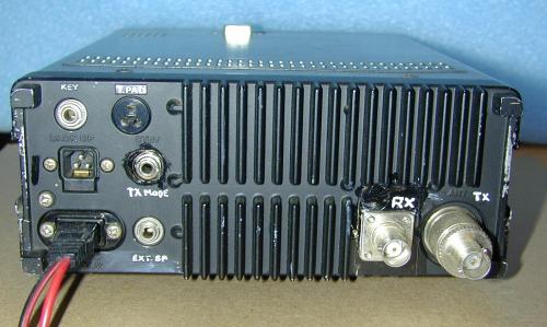
connectors they have available. Here is a picture of the
backpanel to show the end results.
The TX looks like a BNC in this picture because I have an
adapter screwed onto the original antenna connector.
Below is the list of Electrical Changes --
step by step..
TX Power Reduction
-
On Final board (backpanel) lift Connector
1 pin 6 (PC signal) wire and insulated it.
This disables the HI/LOW button and forces low power
always. Mod Picture.This should
make step # 2 unnecessary, but I haven't undone it myself
yet so I will list it now...
-
Lift RX board Connector 10 pin 4 (SOC)
wire and insulated it. This makes SSB mode go to low power
from LOW position of HI/LOW. Originally SSB wasn't affected
by the HI/LOW button (always full power). Mod Picture.
-
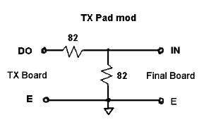
Add attenuator pad in the TX RF path between TX board and
Final board. This is made with two 82 ohm resistors as
shown in this schematic.
The signal passes through a coax that slips onto two pins
on each of the two boards. I removed the connections on
the TX board and did not modify the cable at all. I built
the attenuator with its own female connector for the DO
pin of the TX board. Using a thick wire a made a pin to
slip into the connector for the center wire of the coax.
A connection was soldered to the ground connector of the
coax, but this could be removed without damage, and the
coax used again as originally designed. The pad resistors
were insulated and the whole pad place into a small piece
of shrink tubing. This pictures
page shows details on this construction.
-
With the Pad installed per #3, adjust CW output level to
about +20 dBm using VR4 pot on the TX board.
Convert NB button to TX
-
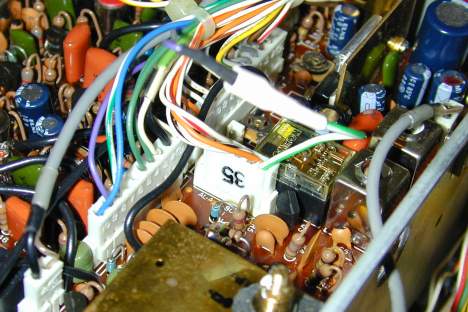
Lift RX board Connector 6 pin 6 (NB).
Cover pin with shrink tubing, but leave end open. Add and
extra wire onto Connector 35 pin 5 (ST).
You may have to pull this wire from the connector, so you
can solder the new wire along with the existing wire, then
reinsert into Connector 35. Connect this
new wire into the connector removed from Connector
6 pin 6 (NB) wire. Mod
picture.
This makes NB act as a
TX switch. When sending CW it can be
advantageous to have a way to force TX mode. The carrier
is not forced unless the CW key is closed but this forces
the TX signal (next mod) while NB is pressed.
Provide TX Mode output control signal
This addition provides a control for TX/RX switching from
the TR 9000. The STBY connector was removed and changed to
a more common socket to export this signal. The change was
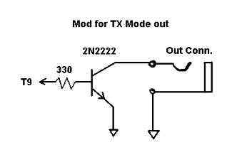
implemented as a single NPN transistor that pulls the
output to ground while the TR 9000 is in transmit mode. The
following picture shows the simple circuit.
-
Change STBY connector on backpanel to 3.5 mm socket.
Insulate the wires removed.
-
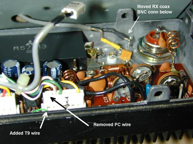
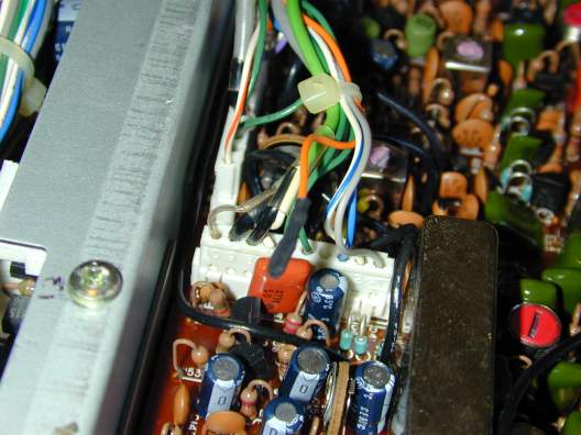
Connect a wire onto the Final board at Connector
1 pin 5 (T9). The following picture link
is not great as a guide, but shows the general location as
a small green wire labeled 'Added T9 Wire'. Mod picture.
-
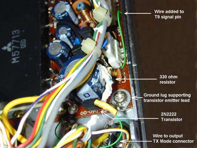
Build the circuit shown above. I mounted the transistor by
soldering the emitter lead to a ground tab that was added
on one of the Final board mounting screws. The 330 ohm
resistor is connected to the wire that was added in step
#2. After soldering the other end of the resistor to the
2N2222 base, I secured it with a dab of silicon RTV
adhesive. Connect the 2N2222 collector to the output socket
with a wire and ensure that the socket is also grounded.
Mod Picture.
Separate RX Input connector
I wanted to separate the TX and RX paths for use as an IF.
If this section is skipped, the radio should function
normally with TX and RX both through the antenna connector.
-
Install the RX BNC connector on the backpanel. As mentioned
at the top of this page, this requires removal of fins from
the backpanel and (for my layout) some other milling to
provide access for mounting on the inside of the back
panel. I completely removed the backpanel from the radio to
perform this work. Mod picture.
-
On the Final board, remove the RX Coax from Connector
1 pins 2, 3 (RA, E). Mod picture.
-
Solder one leg of a 0.01 mfd capacitor to the center
connection of the new BNC. Cut the other leg short. Solder
a short solid wire to a ground tab on the BNC.
-
Plug the center conductor of the RX cable (from step # 2)
onto the free leg of the capacitor (from step #3). Plug the
RX coax ground connector onto the short ground wire.
Mod picture.