Description
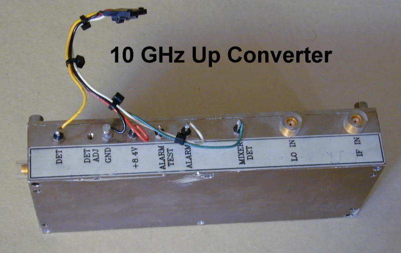
An up converter that takes an IF input frequency of about 375 MHz and converts it to an output in the high 10 GHz area. Output power is about 1 watt.
Conversion Notes for 410002 10 GHz Up Converter
-----------------------------------------------

I converted one of these for use on the US ham bands at 10368 MHz.

The final amps produce about 1W with 10 dBm in. The designed operation
frequency is in the range of 10. to 10.8 GHz.  The IF input is 375 MHz.
I used it at about 310 MHz. The IF input will not work at 2M if. It might
be possible to tune this down, but I never tried.

There is a detector on the output that provides a DC voltage proportional
to the output power.  I have lost my notes on the voltage range, but I have
used it to drive a meter.

Modification is difficult.  The circuitry is wire bonded ceramic and fairly
small.  In the up conversion, there is a hairpin filter that limits the band
pass.  I modified this filter to lower the operation frequency to 10368.  The
following describes the process.

To retune the filters down, I used a scaler analyser.  I swept the IF input
through a range in the area of 300 MHz and provided a fixed LO input for
high-side mixing to 10368 output.  Actually, I started with a higher LO to
give output in the designed frequency output of the converter block.

I cut small pieces of copper foil that were about the width of the traces in
the hairpin filter.  I put these on each of the hairpin traces and gradually
pushed them out to extend the traces, while lowering the LO frequency, until
by carefull tweaking of the position of each foil piece, I got the pass band
flat around the ham band frequencies.

For the final tuning, I used the silver "ink" from a Circuit Works conductive
pen. I removed the tip of the pen by unscrewing it (left hand thread!) and
dumping a small amount into a small container. Using a small steel quill pen
or a piece of wire, I was able to use this "ink" to paint extension traces
where required in the circuit for tuning.

To accomplish the final tuning, I removed one piece of copper foil and --
watching the analyser bandpass -- painted silver extensions to match the
previously attained response. This is a touchy and tedious process. The
bandpass changes slightly as the ink dries, so may need some retouching.
If the traces are made too long, the ink must be scrapped off and (possibly)
redone.

While the circuit is opened, great caution is required.  The transistors are
connected with very fine gold wire.  One must be very carefull not to touch
any of these bond wires while the case is opened.

Retuning the filters is a difficult process and requires at minimum a scaler
sweeper and detector in the 10 GHz output range.

Depending on the circuit trace metal (gold or silver) and soldering materials
available, it is possible that the copper flakes could be soldered in place
rather than using the silver ink as the permanant method.  I used soldering
on one set of silver filters, but had no success and went to the ink on a
gold trace filter.

-----

I never investigated this, but it may be possible to retune the low frequency
stage for operation on a different frequency than the designed range near 300
MHz. If anyone has success on this, please contact me and I will post the
information.
Above information as a text file. -- 10GupNotes.txt
Picture